High Power Optical Fiber Cable
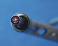
The high power delivery fiber cable is individually designed for specific application. Different fiber core diameter, connector and protection tubing are available.
- Temperature range: -40°C to 350°C
- Single mode or multimode fiber
- Wavelength range: 350 nm – 2300 nm
- Fiber core diameter: 10 µm – 1000 µm
- Numerical aperture: 0.10 – 0.49
SMA 905 standard
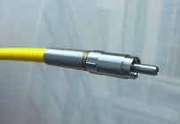
- Ferrule: copper or arcap
- Ferrule diameter: 3.17 mm
- Standard or free-standing fiber tip
- Power: up to 50 W CW
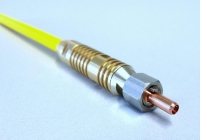
High power SMA 905
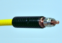
- Ferrule: copper alloy
- Ferrule length: 3.17 mm
- Free-standing fiber tip
- Power: >50 W CW
- Options: key, thermistor, endcap, mode stripper
LD80 compatible connector passive cooling
- Ferrule diameter: 4 mm
- Free-standing fiber tip
- Power: up to 500 W
- Options: key, thermistor, endcap, mode stripper
LD80 compatible connector water cooling
- Active water cooling
- Ferrule diameter: 4 mm
- Free-standing fiber tip
- Power: up to 1 kW
- Options: key, thermistor, endcap, mode stripper
Optical Fiber Nx1 Combiner
High power Nx1 pump combiner for direct pumping
| Configuration | Pump input fiber | Output fiber | Power per input1 | Min. efficiency | Package |
|---|---|---|---|---|---|
| 2×1 | 105/125 µm, 0.15NA | 105/125 µm, 0.22NA | 50 W | 90% | P32 |
| 2×1 | 105/125 µm, 0.15NA | 200/220 µm, 0.22NA | 50 W | 95% | P32 |
| 2×1 | 105/125 µm, 0.22NA | 200/220 µm, 0.22NA | 50 W | 95% | P32 |
| 2×1 | 200/220 µm, 0.22NA | 400/440 µm, 0.22NA | 50 W | 95% | P32 |
| 3×1 | 105/125 µm, 0.12NA | 105/125 µm, 0.22NA | 50 W | 0,85 | P32 |
| 3×1 | 105/125 µm, 0.15NA | 200/220 µm, 0.22NA | 50 W | 0,95 | P32 |
| 3×1 | 105/125 µm, 0.22NA | 200/220 µm, 0.22NA | 50 W | 0,93 | P32 |
| 3×1 | 200/220 µm, 0.22NA | 400/440 µm, 0.22NA | 50 W | 0,95 | P32 |
| 4×1 | 105/125 µm, 0.15NA | 200/220 µm, 0.22NA | 80 W | 0,95 | P32 |
| 4×1 | 105/125 µm, 0.22NA | 220/242 µm, 0.22NA | 50 W | 0,9 | P32 |
| 4×1 | 200/220 µm, 0.22NA | 400/440 µm, 0.22NA | 150 W | 0,9 | P32 |
| 7×1 | 105/125 µm, 0.12NA | 200/220 µm, 0.22NA | 80 W | 0,93 | P32 |
| 7×1 | 105/125 µm, 0.15NA | 200/220 µm, 0.22NA | 80 W | 0,9 | P32 |
| 7×1 | 105/125 µm, 0.22NA | 400/440 µm, 0.22NA | 100 W | 0,96 | P32 |
| 13×1 | 105/125 µm, 0.22NA | 400/480 µm, 0.22NA | 50 W | 0,9 | P32 |
| 19×1 | 105/125 µm, 0.15NA | 400/440 µm, 0.22NA | 50 W | 0,9 | P32 |
| 19×1 | 105/125 µm, 0.22NA | 600/720 µm, 0.22NA | 60 W | 0,93 | P32 |
1. Customized configuration and higher input power are available upon request.
High power Nx1 pump combiner with double-clading fiber output
| Configuration* | Pump input fiber | DC output fiber1 | Power per input2 | Min. efficiency | Package |
|---|---|---|---|---|---|
| 2×1 | 105/125 µm, 0.15NA | x/125 | 100 | 95 | P32 |
| 2×1 | 105/125 µm, 0.22NA | x/125 | 100 | 95 | P32 |
| 2×1 | 200/220 µm, 0.22NA | x/250 | 100 | 95 | P32 |
| 3×1 | 105/125 µm, 0.15NA | x/125 | 100 | 95 | P32 |
| 3×1 | 105/125 µm, 0.22NA | x/125 | 100 | 95 | P32 |
| 3×1 | 200/220 µm, 0.22NA | x/250 | 100 | 95 | P32 |
| 7×1 | 105/125 µm, 0.15NA | x/125 | 80 | 93 | P32, P33 |
| 7×1 | 105/125 µm, 0.22NA | x/250 | 80 | 96 | P32, P33 |
| 7×1 | 200/220 µm, 0.22NA | x/400 | 200 | 96 | P33 |
| 19×1 | 105/125 µm, 0.15NA | x/200 | 80 | 95 | P32, P33 |
| 19×1 | 105/125 µm, 0.22NA | x/250 | 80 | 95 | P32, P33 |
| 19×1 | 105/125 µm, 0.22NA | x/400 | 80 | 95 | P32, P33 |
1. x: doped fiber core diameter
2. Customized configuration and higher input power are available upon request.
Optical fiber Pump+Signal combiner
Multimode Pump+Signal combiner
| Configuration | Pump fiber | Signal fiber | Output fiber | Power per input | Singal insertion loss | Min. efficiency | Package |
|---|---|---|---|---|---|---|---|
| (2+1)x1 | 105/125 µm, 0.22NA | x/125 SC or DC | x/125 DC | 50 W | 0.35 dB | 0,9 | P30,P31,P32 |
| (2+1)x1 | 105/125 µm, 0.22NA | x/125 SC or DC | y/125 DC | 50 W | 0.7 dB | 0,9 | P30,P31,P32 |
| (2+1)x1 | 105/125 µm, 0.22NA | x/125 SC or DC | y/250 DC | 50 W | 0.7 dB | 0,93 | P32 |
| (2+1)x1 | 105/125 µm, 0.22NA | x/250 SC or DC | x/250 DC | 50 W | 0.5dB | 0,93 | P32 |
| (2+1)x1 | 200/220 µm, 0.22NA | x/250 SC or DC | x/250 DC | 50 W | 0.5dB | 0,9 | P32 |
| (2+1)x1 | 200/220 µm, 0.22NA | x/400 DC | x/400 DC | 50 W | 0.5 dB | 0,9 | P32 |
| (6+1)x1 | 105/125 µm, 0.15NA | x/125 SC or DC | x/125 DC | 25 W | 0.7 dB | 0,9 | P32 |
| (6+1)x1 | 105/125 µm, 0.15NA | x/125 SC or DC | y/125 DC | 25 W | 0.7 dB | 0,93 | P32 |
| (6+1)x1 | 105/125 µm, 0.22NA | x/125 SC or DC | y/250 DC | 50 W | 0.7 dB | 0,93 | P32 |
| (6+1)x1 | 200/220 µm, 0.22NA | 20/400 DC | 20/400 DC | 100 W | 0.7 dB | 0,95 | P32, P33 |
| (18+1)x1 | 105/125 µm, 0.15NA | x/125 SC or DC | x/200 DC | 50 W | 0.8 dB | 0,95 | P32, P33 |
| (18+1)x1 | 105/125 µm, 0.22NA | x/125 SC or DC | x/400 DC | 50 W | 0.8 dB | 0,95 | P32, P33 |
Notes:
1. x, y= different core diameter ;
2. SC: Single Cladding, DC: Double Cladding
Multimode Pump+Polarisation Maitaining Signal combiner
| Configuration | Pump fiber | Signal fiber | Output fiber | Power per input | Singal insertion loss | Min. efficiency | Package |
|---|---|---|---|---|---|---|---|
| PM (2+1)x1 | 105/125 µm, 0.22NA | x/125 SC or DC | x/125 DC | 50 W | 0.35 dB | 0,9 | P30,P31,P32 |
| PM (2+1)x1 | 105/125 µm, 0.22NA | x/125 SC or DC | y/125 DC | 50 W | 0.7 dB | 0,9 | P30,P31,P32 |
| PM (2+1)x1 | 105/125 µm, 0.22NA | x/125 SC or DC | y/250 DC | 50 W | 0.7 dB | 0,93 | P32 |
| PM (2+1)x1 | 105/125 µm, 0.22NA | x/250 SC or DC | x/250 DC | 50 W | 0.5 dB | 0,93 | P32 |
| PM (2+1)x1 | 200/220 µm, 0.22NA | x/250 SC or DC | x/250 DC | 50 W | 0.5 dB | 0,9 | P32 |
| PM (2+1)x1 | 200/220 µm, 0.22NA | x/400 DC | x/400 DC | 50 W | 0.5 dB | 0,9 | P32 |
| PM (6+1)x1 | 105/125 µm, 0.15NA | x/125 SC or DC | x/125 DC | 25 W | 0.7 dB | 0,9 | P32 |
| PM (6+1)x1 | 105/125 µm, 0.15NA | x/125 SC or DC | y/125 DC | 25 W | 0.7 dB | 0,93 | P32 |
| PM (6+1)x1 | 105/125 µm, 0.22NA | x/125 SC or DC | y/250 DC | 50 W | 0.7 dB | 0,93 | P32 |
| PM (6+1)x1 | 200/220 µm, 0.22NA | 20/400 DC | 20/400 DC | 100 W | 0.7 dB | 0,95 | P32, P33 |
| PM(18+1)x1 | 105/125 µm, 0.15NA | x/125 SC or DC | x/200 DC | 50 W | 0.8 dB | 0,95 | P32, P33 |
| PM (18+1)x1 | 105/125 µm, 0.22NA | x/125 SC or DC | x/400 DC | 50 W | 0.8 dB | 0,95 | P32, P33 |
Notes:
1. x, y= different core diameter ;
2. SC: Single Cladding, DC: Double Cladding
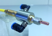
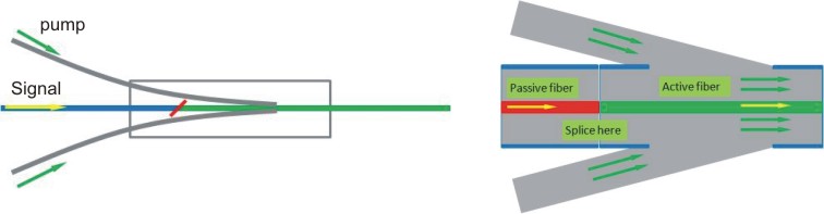
Doped Fiber Combiner, MPSC(N+1)x1
Doped fiber combiner combines 1 or 2 pump power source into a doped fiber directly. The splicing point is behind the coupling region, which has two advantages over standard combiner:
1) Customer only needs splice one time with doped fiber at combiner signal side.
2) The coupling region is behind splicing point, the isolation (backward signal to pump) is much lower than normal passive combiner to protect pump LD.
| Configuration | Pump fiber | Signal fiber | Output fiber | Power per input | Singal insertion loss | Min. efficiency | Package |
|---|---|---|---|---|---|---|---|
| (2+1)x1 | 105/125 µm, 0.22NA | 6/125 SC or DC | 6/125 DC | 50 W | 0.5 dB | 0,9 | P31,P32 |
| (2+1)x1 | 105/125 µm, 0.22NA | 8/125 SC or DC | 8/125 DC | 50 W | 0.5 dB | 0,9 | P31,P32 |
| (2+1)x1 | 105/125 µm, 0.22NA | 10125 SC or DC | 10/125 DC | 50 W | 0.5 dB | 0,9 | P31, P32 |
| (2+1)x1 | 105/125 µm, 0.22NA | 12/125 SC or DC | 12/125 DC | 50 | 0.5 dB | 0,9 | P31, P32 |
| (2+1)x1 | 105/125 µm, 0.22NA | 25/250 SC or DC | 25/250 DC | 50 | 0.5 dB | 0,93 | P32 |
| (2+1)x1 | 105/125 µm, 0.22NA | 30/250 SC or DC | 30/250 DC | 50 | 0.5 dB | 0,9 | P32 |
Polarisation coupler
Polarisation insensitve PM coupler (PIPMC 1×2 or 2×2)
The PIMPMC can work at designed coupling ratio at both fast and slow axis.
| Parameters | Unit | P grade | A grade | P grade | A grade |
|---|---|---|---|---|---|
| Wavelength range | nm | 980,1060 ±20 | 1310, 1480, 1550 ±20 | ||
| Excess loss (typical) | dB | 0.6 | 0.8 | 0,4 | 0.6 |
| Excess loss | dB | ≤0.8 | ≤1.0 | ≤0.6 | ≤0.8 |
| Polarisation dependent loss | dB | ≤0.1 | ≤0.2 | ≤0.1 | ≤0.2 |
| Polarisation extinction ratio | dB | ≥18 | ≥15 | ≥20 | ≥14 |
| Operating power | W | 2 | |||
| Package | W | Φ3xL54 or other package size | |||
Polarisation maintaining coupler (1×2 or 2×2)
PMC is built with FBT technique with PM fiber and is widely used for optical sensors and optical gyro, etc.
Its coupling efficiency can be easily adjusted upon customer’s request.
| Parameters | Unit | P grade | A grade | P grade | A grade |
|---|---|---|---|---|---|
| Wavelength range | nm | 980,1060 +/-20980,1060 ±20 | 1310, 1480, 1550 ±20 | ||
| Excess loss (typical) | dB | 0.6 | 0.8 | 0,4 | 0.6 |
| Excess loss | dB | ≤0.8 | ≤1.0 | ≤0.6 | ≤0.8 |
| Polarisation dependent loss | dB | ≤0.1 | ≤0.2 | ≤0.1 | ≤0.2 |
| Polarisation extinction ratio | dB | ≥18 | ≥15 | ≥20 | ≥14 |
| Operating power | W | 2 | |||
| Package | W | Φ3xL54 or other package size | |||