GIP Technology Corporationについて
GIP Tekは、台湾で1999年に創業を始めた光学関連部品・製品のメーカーです。
1)ファイバーレーザー、2)アンプリファイアー、3)ファイバーコンポーネントの3分野で事業を展開しています。
当社はGIP Technology Corporationの代理店です。
ラインナップ
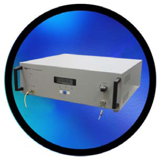
ファイバーレーザー
- 1.0 µm Fiber Laser
- 1.5 µm Fiber Laser
- 1.5 µm Tunable Fiber Laser
- 808 nm High-Power Light source unit
- 976 nm High-Power Light source unit
1.5 µmアンプリファイアー
- EFA-S: EDFA single channel C-band Standard series
- EFA-W: EDFA DWDM C-band series
- CGB/EFA-H: EDFA High-Power series
- CGB/EFA-PM: EDFA Polarization Maintaining Series
- Micro or MSA Gain block Compact series
- AGB/CGB/EFA-V: CATV EDFA
- EFA-T: Combo Amplifier EDFA series
1.0 µmアンプリファイアー
- S-Series: Ytterbium-DFA Standard series
- H-Series: YDFA High-power series
- PM-Series: YDFA Polarization-maintaining series
他のアンプリファイアー
- SOA-Series: Optical Amplifiers
- Raman pump unit
- Low-noise High-power dual EDFA
- Optical Amplifier System
ファイバーコンポーネント Sub-systems
Light sources
- BLS series: Broadband Light sources
- FP-series Light sources
- DFB-series Light sources
- Light Source Unit (O-band)
Dispersion Compensation Unit
Booster
宇宙対応製品
ファイバーレーザー
GIP Technologyは4波長のファイバーレーザー及びおよそ1500 nmで調整可能なファイバーレーザーを生産しています。2波長は高出力可能です。
1.0 µm Fiber Laser
- 1060 nm (1030-1100 nm)
- CW or pulsed operation
- up to 10 W optical average output power
- 5 nm linewidth FWHM
- All-fiber technology
- No water cooling
- RS232 interface
- Collimator and isolator in option
Pulsed mode
- 1064+/-5 nm
- 10-100 kHz
- 10-100 ns
用途
- Laser marking
- LIDAR
- Sensing
Available in 110-220V AC and in 5 to 24V DC versions.
1.5 µm Fiber Laser
- 1550 nm (1530-1565 nm)
- CW or pulsed operation
- up to 5W optical average output power
- 5 nm linewidth FWHM
- All-fiber technology
- No water cooling
- RS232 interface
- Collimator and isolator in option
Pulsed mode
- 1550+/-5 nm
- 10-100 kHz
- 10-100 ns
用途
- Laser marking
- LIDAR
- Sensing
Available in 110-220V AC and in 5 to 24V DC versions.
1.5 µm Tunable Fiber Laser
- 1530-1560 nm
- CW / Timing control
- Linear polarization
- up to 1W optical average output power
- 10MHz linewidth
- All-fiber technology
- No water cooling
Pulsed mode
- 1064+/-5 nm
- 10-100 kHz
- 10-100 ns
用途
- High power seed laser source
- Component testing
- Sensing
- Spectroscopy
Available in 110-220V AC version.
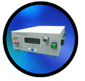
808 nm High-Power Light source unit
- 808 nm +/-10 nm
- CW operation
- up to 20W optical average output power
- Multiple Fiber power combined technology
- Front panel LCD and status LED
- RS232 interface
用途
- Solid-state laser pumping
- Medical or dental applicatio ns
- Industrial applicatio ns
- Defense applicatio ns
Available in 100-240 V version.
976 nm High-Power Light source unit
- 976 nm +/-5 nm
- CW operation
- up to 25W optical average output power
- Multiple Fiber power combined technology
- Front panel LCD and status LED
- Air cooling
- RS232 interface
- Pointing red beam option
用途
- Solid-state laser pumping
- Medical or dental applicatio ns
- Industrial applicatio ns
- Defense applicatio ns
Available in 100-240 V version.
1.5 µmアンプリファイアー
EFA-S: EDFA single channel C-band Standard series
遠距離通信におけるシングルチャンネル用途用
特徴
- 1528-1562 nm
- input power range:
- Booster version: -10 to +10 dBm
- Pre version: -30 to -10 dBm
- Saturated output power (including ASE):
- Booster vers. 23 dBm
- Pre vers. : 13 dBm
- Signal gain:
- Booster vers. 25 dB
- Pre vers. 30 dB
- Bit-rate transparency
- Low-noise figure
- Optically isolated input and output
- Front panel LCD and status LED
- RS-232 or Ethernet (SNMP)
- redundant power supply
用途
- Access, metro and long-haul networks
- Single-channel and narrow band networks
- Power compensqtion of OADM and OXC systems
- Booster and pre-amplifier amplification
Available in 100-240 V AC and -48 V DC versions.
EFA-W: EDFA DWDM C-band series
ダイナミックDWDM用途におけるゲインフラット化及びローノイズオペレーション用。
特徴
- 1530-1563 nm
- input power range:
- Booster version: -10 to +10 dBm
- In-line version: -20 to 0 dBm
- Pre version: -30 to -10 dBm
- Saturated output power (including ASE):
- Booster vers.: 24 dBm
- In-line vers. : 24 dBm
- Pre vers. : 17 dBm
- Signal gain:
- Booster: 20 dB
- In-line: 30 dB
- Pre: 30 dB
- Automatic gain control (AGC)
- Bit-rate transparency
- Low-noise figure, Flat gain
- Optically isolated input and output
- Front panel LCD and status LED
- RS-232 or Ethernet (SNMP)
- redundant power supply
用途
- DWDM networks
- SAN applicatio ns
- Metropolitan WAN networks
- Long-haul transport systems
Available in 100-240 V AC and -48V DC versions.
CGB/EFA-H: EDFA High-Power series
CATVまたはPON配信システム用途用
特徴
- 1545-1562 nm
- input power range: -10 to +10 dBm
- Saturated output power (including ASE): up to 36 dBm
- Output ports number: 1, 4, 8, 16, 32
- Automatic gain control (AGC)
- Low-noise figure
- Optically isolated input and output
- Front panel LCD and status LED
- RS-232 or Ethernet (SNMP)*
用途
- Analog and digital CATV transmission systems
- PON systems
- Long-haul transmission systems
- Instrumentation
*Available in 100-240 V AC with RS-232 and Ethernet (CGB-H version), or +5, +12V DC with RS-232 only (EFA-H version).
CGB/EFA-PM: EDFA Polarization Maintaining Series
高速及び広帯域幅用途用
特徴
- 1530-1562 nm
- input power range: -10 to +10 dBm
- Saturated output power (including ASE): up to 25 dBm
- Low-noise figure
- Optically isolated input and output
- Front panel LCD and status LED
- RS-232
用途
- Ultra-high speed systems
- Wide band PM transmission systems
- Optical sensors
- Test and Instrument measuements
- Lab research
Available in 100-240 V AC (CGB version), or +5V DC (EFA version).
Micro or MSA Gain block Compact series
成長metro market用
特徴
- Micro (40x64x12 mm) or MSA (70x90x15 mm) compact CGB size; MSA (70x90x12mm) compact AGB size
- +5.0 or +3.3 Vdc operating voltage
- Low-noise figure
- Optically isolated input and output
- Single-mode fibered
用途
- Access, metro and long-haul networks
- Single-channel and narrow-band networks
- Power compensation of OADM and OXC systems
- Booster and pre-amplifier amplification
CGB-C series: Single Channel C-Band EDFA, Micro controlled Gain Block
| Operating wavelength range | 1530-1560 nm |
|---|---|
| Input power range |
Booster version: -10, +5 dBm Pre Ampl version: -30, -10 dBm |
| Saturated output power (including ASE) |
Booster: 17 dBm Pre: 13 dBm |
| Signal gain | Pre: 30 dB |
AGB-C series: Single Channel C-band EDFA, MSA Active Gain Block
| Operating wavelength range | 1528-1562 nm |
|---|---|
| Input power range |
Booster version: -10, +10 dBm Pre Ampl version: -25, -10 dBm |
| Saturated output power (including ASE) |
Booster: 21 dBm Pre: 13 dBm |
Signal gain |
Booster: 25 dB Pre: 30 dB |
AGB-C series: DWDM C-band EDFA, MSA Active gain block
| Operating wavelength range | 1528-1563 nm |
|---|---|
| Input power range |
Booster version: -10, +10 dBm Pre Ampl version: -30, -10 dBm |
| Saturated output power (including ASE) |
Booster: 21 dBm Pre: 13 dBm |
| Signal gain |
Booster: 17 dB Pre: 30 dB |
CGB-C series: Single Channel C-Band EDFA, MSA Controlled gain block
| Operating wavelength range | 1528-1562 nm |
|---|---|
| Input power range |
Booster version: -10, +10 dBm Pre Ampl version: -30, -10 dBm |
| Saturated output power (including ASE) |
Booster: 21 dBm Pre: 13 dBm |
| Signal gain |
Booster: 25 dB Pre: 30 dB |
CGB-C series: DWDM C-band EDFA, MSA Controlled gain block
| Operating wavelength range | 1528-1563 nm |
|---|---|
| Input power range |
Booster version: -10, +10 dBm Pre Ampl version: -30, -10 dBm |
| Saturated output power (including ASE) |
Booster: 21 dBm Pre: 13 dBm |
| Signal gain |
Booster: 17dB Pre: 30 dB |
AGB/CGB/EFA-V: CATV EDFA
ケーブルテレビ伝送システム用
特徴
- 1540-1560 nm
- input power range: -5 to +10 dBm
- Saturated output power (including ASE):
- AGB-V: 25 dBm
- CGB-V: 25 dBm
- EFA-V: 25 dBm
- Optimum CNR/CSO for AM-VSB CATV transmission
- Low-noise figure
- Optically isolated input and output
- Front panel LCD and status LED
- RS-232 or Ethernet (SNMP)*
- Option for rapid gain control and transient suppression
用途
- CATV / Hybrid fiber coaxial (HFC) network systems
- PON network systems
- Low noise power booster for transport systems
*Available in 100-240 V AC or -48 V DC with RS-232 and Ethernet (EFA version), and +5V DC with RS-232 only (CGB version), and also without power (AGB).
EFA-T: Combo Amplifier EDFA series
SMFシステムでの波長変換及び距離拡張用
特徴
- 1530-1560 nm ITU grid
- Channel spacing: 100 GHz
- Bit rate:
- 100Mbps-2.7 Gbps
- 10G vers: 9.95-11.1 Gbps
- Saturated output power (including ASE): 13-17 dBm
- Front panel LCD and status LED
- RS-232 or Ethernet (SNMP)
- Redundant dual power supply
用途
- Wavelength conversion and distance extension
- Metro WAN networks
- High-speed networks
Available in 100-240 V AC or -48 V DC.
Pulse Series and Customization
お問い合わせ下さい。
1.0 µmアンプリファイアー
S-Series: Ytterbium-DFA Standard series
遠距離通信におけるシングルチャンネル用途用
特徴
- 1030-1100 nm
- input power range: -30 to 0 dBm
- Saturated output power (including ASE): up to 20 dBm
- Adaptor with shutter
- Optically isolated input and output
- Front panel LCD and status LED
- RS-232
用途
- Detection system
- Sensing
Available in 100-240 V AC version.
H-Series: YDFA High-power series
遠距離通信におけるシングルチャンネル高出力用
特徴
- 1030-1100 nm
- input power range: 0 to 10 dBm
- Saturated output power (including ASE): 30 dBm
- Optically isolated input and output
- Front panel LCD and status LED
- RS-232
用途
- Detection system
- Sensing
Available in 100-240 V AC version.
PM-Series: YDFA Polarization-maintaining series
遠距離通信におけるシングルチャンネル用途用
特徴
- 1030-1100 nm
- input power range: 0 to 10 dBm
- Saturated output power (including ASE): up to 20 dBm
- Optically isolated input and output
- Front panel LCD and status LED
- RS-232
用途
- Detection system
- Sensing
Available in 100-240 V AC version.
Customization
お問い合せ下さい
他のアンプリファイアー
SOA-Series: Optical Amplifiers
1300 nm通信システム用
特徴
- 1280-1340 nm
- input power range: -20 to 0 dBm
- Saturated output power (including ASE): 10 dBm
- Signal gain: 16 dB
- SOA automatic shutdown
- Optically isolated input and output
- Front panel LCD and status LED
- RS-232 or Ethernet (SNMP)
- Redundant dual power supply
用途
- Metropolitan WAN network systems
- Access network systems
- Submarine transmission systems
- High speed transmission systems
Available in 100-240 V AC or -48V DC versions.
Raman pump unit
長距離且つ高帯域幅DWDMネットワークにおける、被配信ラマンアプリケーション用
特徴
- 1528-1565 nm
- On-Off gain: 10 dB
- Flattened Raman gain
- Front panel LCD and status LED
- RS-232 and Ethernet (SNMP)*
- Redundant dual power supply
用途
- 10 Gb/s and 40 Gb/s transmission systems
- Long-haul DWDM telecommunication systems
- High channel count systems
- Increase regenerator spacing
Available in 100-240 V AC or -48 V DC versions.
Low-noise High-power dual EDFA
高出力シングルチャンネル用途
特徴
- 1530-1563 nm
- Channel spacing: 100 GHz
- input power range:
- Pre Amp vers.: -30, -20 dBm
- Power Amp vers.: +5, +20 dBm
- Saturated output power (including ASE):
- Pre Amp: 10 dBm
- Power Amp: 30 dBm
- Extremely low noise figure
- Optional reflection shutdown function
用途
- High-power R&D experiment
- Fiber laser applicatio ns
- Optical switching applicatio ns
- …
Available in 100-240 V AC.
ファイバーコンポーネント Sub-systems
Optical Amplifier System
お問い合わせください(上記SOAをご参照ください)
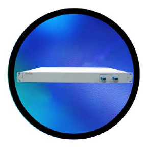
Optical Protection Systems
GIPは1-RU オプティカルプロテクションスイッチ(OPS)及び6-RU レストレーションスイッチシステム(RSS)を提供致します。
これらは標準及びTシリーズ(1100 nm~1600 nmを受けて変換/増幅できるGBFファイバーエクステンダーモジュールを含む)で有効です。
- 1310+/-20 nm and 1550+/-20 nm
- OSC wavelength: 1625+/-30 nm
- CISPR22 Class A compliant
- Auto / Semi-Auto / Manual switching mode
- RS232 interface and Ethernet (SNMP)
- Standard:
- Insertion loss: 6 dB
- T-Series:
- Bit rate: 1.25 or 2.5 Gbps
- Output power: -6 dBm
用途
- Optical path monitoring and recovery
- Local area networks
- Access/metropolitan area network
Available in 100-240 V AC or -48V DC versions.
Fiber Extenders
遠距離通信システム帯域 へのオプティアカルーオプディカル変換用
- reception:
- 1260-1620 nm
- input power: -8 to 0 dBm
- transmission:
- CWDM or C-band DWDM 100GHz ITU grid
- Output power: 0 dBm
- Bit rate: 100-2700 Mbps
- Multiple data rates
- RS232 interface and Ethernet (SNMP)
用途
- Local area networks
- Access/metropolitan area network
Available in 100-240 V AC or -48 V DC versions.
Bright-Edge 20T and 20P
一方向性WDM用途用。20Tはトランスポンダーを含みます。
20P
- MPI side:
- 1471-1611 nm with 20 nm spacing
- input power: -20 to 8 dB
- CPE side:
- 1511-1611 nm with 20 nm spacing
- Output power: 0 dBm
20T
- MPI side:
- 1471-1611 nm with 20 nm spacing
- output power: -3 dB/channel
- CPE side:
- 1511-1611 nm with 20 nm spacing
- input power: -8 dBm
- Bit rate: 2.488 Gbps
- Compliant with specifications for SONET/SDH
- RS232 interface and Ethernet (SNMP)
- Redundant dual power supply
用途
- Local area networks
- Access/metropolitan area network
Available in 100-240 V AC or -48V DC versions.
Light sources
BLS series: Broadband Light sources
Provides a stable output in the 1060 nm, C / L /C+L bands.
- 1060 nm, C / L /C+L bands
- Output power:
- 1040-1075 nm: 10 dBm
- 1528-1562 nm: 15 dBm
- 1530-1610 nm: 20 dBm
- All-fiber technology
- Front panel LCD and status LED
用途
- Optical components testing
- Optical fiber characterization
- Optical measurements systems
- Fiber optic sensing
Available in 100-240 V AC version.
FP-series Light sources
FPレーザーダイオードの駆動及びテスト用
- 1290-1330 nm or 1520-1580 nm
- Output power: 1 mW
- Spectral width: 3 nm
- Diode temperature monitoring
- TEC included
- Front panel LCD and status LED
用途
- Optical components testing
- Optical fiber characterization
- Optical measurements systems
Available in 100-240 V AC version.
DFB-series Light sources
DFBレーザーダイオードの駆動及びテスト用
- 1480-1500 nm or 1530-1560 nm or 1570-1610 nm
- Output power: 1-40 mW
- Spectral width: 5 nm
- Diode temperature monitoring
- TEC included
- Front panel LCD and status LED
用途
- Optical components testing
- Optical fiber characterization
- Optical measurements systems
Available in 100-240 V AC version.
Light Source Unit (O-band)
Laser Source Unit is reliable and stable light source. It is easy to use for research and optical component testing.
In addition, these units also provide a user-friendly status monitoring via LED indicators.
The bench-top package size serves the area size, can be used in the components or sub-assembly manufacturing as well as research and development (R&D) environments.
O-band (1260 nm-1360 nm) light sources are mainly used in silicon photonics testing applications in the following areas.
1. Basic optical characterisation of silicon photonics devices
-
Waveguide Loss Measurement
Measure transmission losses in silicon waveguides using an O-band light source to verify their low attenuation properties. -
Spectral Response Measurement
Evaluate the spectral characteristics of ring resonators and filters while sweeping the wavelength of the O-band. -
Insertion Loss & Return Loss Measurement
Optical coupling efficiency and reflective properties are measured to check the performance of the device.
2. Evaluation of silicon photonics modulators and switches
-
Modulation Test
O-band sources are used to assess modulation efficiency, linearity and bandwidth, e.g. in Mach-Zehnder modulators. -
Optical Switch Response Test
The response time and switching efficiency of silicon photonic switches are evaluated in O-band.
3. Photo-detector (PD) and receiver side evaluation
-
Responsivity Test
Measure the sensitivity and detection efficiency of a photodetector using an O-band light source. -
Dark Current & Noise Measurement
Check low noise and high SNR (signal-to-noise ratio) in O-band operation.
4. Packaging and assembly tests
-
Optical Coupling Test
Evaluate the coupling efficiency between the fibre and the silicon photonics chip and check the stability after packaging. -
Thermal Stability Test
Ensure reliability by checking changes in performance under different temperature conditions.
5. Communications and interconnect testing
-
Data Center Interconnect Test
The O-band is the main wavelength band for short-range data centre-to-data centre connectivity, and is used to evaluate e.g. 400G/800G modules. -
Optical Link Integrity Test
Assess the quality of optical communication links by checking for low bit error rate (BER) and stability.
In general, O-band light sources are an essential tool in the development, evaluation and production of silicon photonics devices and are widely used to verify optical properties, modulation and detection characteristics, packaging and communication performance.
Dispersion Compensation Unit
DCU for G.652 fibers
従来のG.652ファイバー若しくは長距離光学伝送システムで生じる正分散を有する伝送ファイバーの分散補償用
- Relative Dispersion slope @1550 nm: 0.0036 +/-20%
- Length of G.652 compensated:
- 10 km : Dispersion @1550 nm= -170 ps/ nm
- 40 km : Dispersion=-680 ps/ nm
- 80 km : Dispersion=-1360 ps/ nm
- 100 km : Dispersion=-1700 ps/ nm
- Low insertion loss
- Low PMD
用途
- High speed transmission systems
- Long-haul telecommunication systems
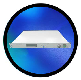
Booster
S-series controlled gain block (CGB)
Sシリーズ・コントロールド・ゲイン・ブロック(CGB)は、ハイパワー・シングルチャンネル・アプリケーション用に設計されています。これらのシリーズは、雑音指数を最小化しながら、最大信号利得と飽和出力電力を生成するために、特別でユニークかつ柔軟な構造を取り入れています。
これらの重要なアンプ・パラメーターを最適化することで、このモジュールは高品質の通信プラットフォームに容易に導入することができます。
また、RS-232を採用した電気的インターフェースにより、ユーザーフレンドリーなステータス監視が可能です。
- 高飽和出力
- コンパクトサイズ
- 光絶縁入出力ポートにより、コネクタ反射によるシステムの影響を最小化
- 入出力信号モニタリング
- RS-232 によるローカル監視
- 自由空間光通信
- リモートセンシング
- 分散型またはPONシステム
- 光コンポーネント試験
- 計測器
- 研究開発環境
仕様
| 光情報 | Unit | 説明 | |
|---|---|---|---|
| 動作波長 | nm | 1540 ~ 1565 | |
| 入力電力 | dBm | -5 ~ +10 | |
| 飽和出力電力*1,2 | dBm | 33 | |
| 雑音指数*2 | Max | dB | 5.5 |
| 出力電力安定度*3 | Max | dB | ±0.1 |
| ファイバタイプ | SMF-28 with 900μm tube | ||
| ファイバ長 | 1±0.1 | ||
| コネクタ | FC/APC | ||
| 電気情報 | |||
| 電源電圧 | Volt | +12V | |
| 制御モード | APC | ||
| 環境情報 | |||
| 動作ケース温度 | ℃ | -10 ~ 65 | |
| 保存温度 | ℃ | -20 ~ 80 | |
| 相対湿度(結露しないこと) | % | 5 ~ 85 | |
| 冷却方法 | Air FAN + heat sink cooling | ||
| 機械情報 | |||
| 外形寸法*4(L × W × H) | mm | 100 x 95 x 25 | |
*1. 飽和パワーは光信号とASEパワーで構成される。
*2. Pin = 0 dBm、1550nmにて測定。
*3. 室温、APC制御モード、30分ウォームアップ後8時間で測定。
*4. ヒートシンクなし。
宇宙対応製品
高精度ASE光源モジュール(Cバンド)
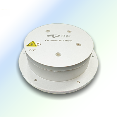
AER-MCASE-00-00-M
GIPテクノロジー 高精度ASE光源(AERMCASE-00-00-M)は、増幅自然放出(ASE)を発生させるためにドープファイバーを利用する技術に基づいています。
FOGフォトニクスは、APC(Automatic Power Control)回路を内蔵し、パワーの変動を正確に制御する、業界をリードするASE光源を提供しています。
さらに、これらの光源はミリタリーグレードの認証に合格しています。その結果、スペクトルやパワーの安定性など優れた性能を発揮し、高精度の光ファイバジャイロ(FOG)に適しています。
特徴
- 高精度
- 優れた温度安定性
- 高い信頼性と安定性
- 低消費電力
- MIL-STD810準拠
アプリケーション
- 光ファイバージャイロスコープ
- 光ファイバーセンシング
- 光計測システム
- 光ファイバー特性評価
仕様
| 光情報 | Unit | 説明 | ||
|---|---|---|---|---|
| 波長 | nm | 1525 ~ 1535 | 1525 ~ 1570 | |
| 出力電力 | Min. | dBm | 5 | |
| 平均波長変動 | Max. | ppm | ± 10 | ± 100 |
| 出力電力安定性 (25℃, 1hr) | Max. | dB | ±0.02 | |
| 出力電力変動 (-20 ~ +60℃) | Max. | % | 6 | |
| リターンロス | Min. | dB | 45 | |
| ファイバータイプ | SMF-28 | |||
| 電気的情報 | ||||
| 動作電圧 | Vdc | 5 | ||
| 制御モード | APC | |||
| 環境情報 | ||||
| 動作温度 | ℃ | -20 ~ +60 | ||
| 保存温度 | ℃ | -20 ~ +80 | ||
| 環境検証 | MIL-STD-810準拠 | |||
| 機械情報 | ||||
| 寸法 | 円形/正方形 | |||
FOGファイバーコイル(PM、Cバンド)
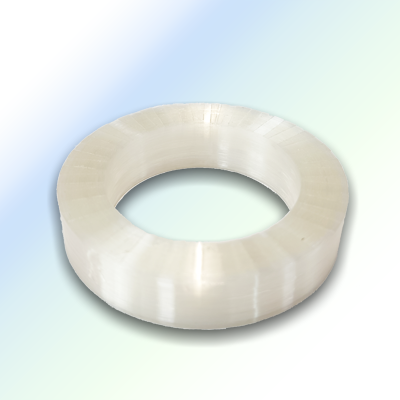
AER-MFCO-PM-00-S
GIPテクノロジーのFOGファイバーコイル(AER-MFCO-PM-00-S)は、光ファイバージャイロスコープ用の高品質ファイバーコイルと技術サービスを提供します。当社の厳格な工程管理と包括的なコイル試験により、各ファイバーコイルは優れた性能パラメータと温度安定性を示します。その結果、GIPテクノロジーが製造する光ファイバジャイロスコープは、全動作温度範囲において卓越したスケールファクターとバイアス安定性を示します。
特徴
- 高 PER
- 低挿入損失
- 小型フットプリント
- カスタマイズ可能なスタンドアロンまたはフレームコイル
- -40℃~+80℃の安定した性能
- MIL-STD810 準拠
アプリケーション
- 光ファイバージャイロ
- 車両測位・航法
- 衛星姿勢制御
- 航空機・船舶姿勢制御システム
仕様
| 光情報 | Unit | 説明 | |
|---|---|---|---|
| 使用波長 | nm | Cバンド | |
| ファイバタイプ | 偏波保持光ファイバー | ||
| ファイバ外径 | 135 μm、165 μm、またはカスタマイズ | ||
| コイルタイプ | フレームレス | ||
| 巻線パターン | モノポール、クアドロポール、ヘキサデカポール、またはカスタマイズ | ||
| ファイバ長*1 | km | 1.5 | |
| コイル内径 | Min. | mm | 35 |
| 層数 | Max. | layers | 100 |
| 接着剤 | UV Glue | ||
| コイルの偏波消光比*2 | Min. | dB | 20 |
| ピグテール片側長さ | Typ. | M | 3 |
| 環境情報 | |||
| 動作周囲温度 | ℃ | -40 ~ +80 | |
| 保存温度 | ℃ | -50 ~ +90 | |
| 相対湿度(非凝縮性) | % | 5 ~ 85 | |
*1. 長繊維化、巻き取りパターンのカスタマイズが可能。
*2. 1550 nm, 25℃, 270 mでの測定値。
宇宙認定ASE光源モジュール(Cバンド)
AER-SCASE-00-00-M
GIPテクノロジーの宇宙仕様ASE光源(AERSCASE-00-00-M)は、ドープファイバを利用した増幅自然放出(ASE)技術に基づいています。
FOGフォトニクスは、業界をリードするASE光源を提供しており、APC(Automatic Power Control)回路を内蔵し、パワーの変動を正確に制御します。
その結果、スペクトルやパワーの安定性など優れた性能を発揮し、高精度の光ファイバジャイロ(FOG)に適しています。
さらに、この広帯域光源は、宇宙環境での信頼性を高めるため、冗長電源アーキテクチャで設計されており、宇宙環境認証を取得しています。
特徴
- 宇宙用
- 優れた温度安定性
- 高い信頼性と安定性
- 低消費電力
アプリケーション
- 光ファイバージャイロスコープ
- 光ファイバーセンシング
- 光計測システム
- 光ファイバー特性評価
仕様
| 光学情報 | Unit | 説明 | |
|---|---|---|---|
| 中心波長*1 | Mea. | nm | 1534±1 |
| スペクトル幅(3dB) | Min. | dB | 12 |
| 出力電力 | Min. | dBm | 3 |
| 出力電力安定性(25℃、1hr) | Max. | dB | ±0.3 |
| リターンロス | Min. | dB | 50 |
| ファイバー・タイプ | SMF-28 | ||
| 電気的情報 | |||
| 動作電圧 | Vdc | 3.3 | |
| 制御モード | APC | ||
| 環境情報 | |||
| 動作温度 | ℃ | -20 ~ +65 | |
| 保存温度 | ℃ | -20 ~ +80 | |
| 環境検証(振動、放射線、熱真空) | ECSS-E-ST-10-03C準拠 | ||
販売実績
(2025年7月更新)
アカデミック
- 大阪大学
- 核融合科学研究所
- 産業技術総合研究所
企業
- 大手自動車メーカー